REMOTE SWITCHING ON AND OFF OF A THREE-PHASE ASYNCHRONOUS MOTOR WITH PUSH BUTTONS
Remote switching on and off of a three-phase asynchronous motor using push buttons enables efficient and safe motor operation from a distance. This method is widely used in industrial settings to enhance practicality and ensure safety in the workplace.
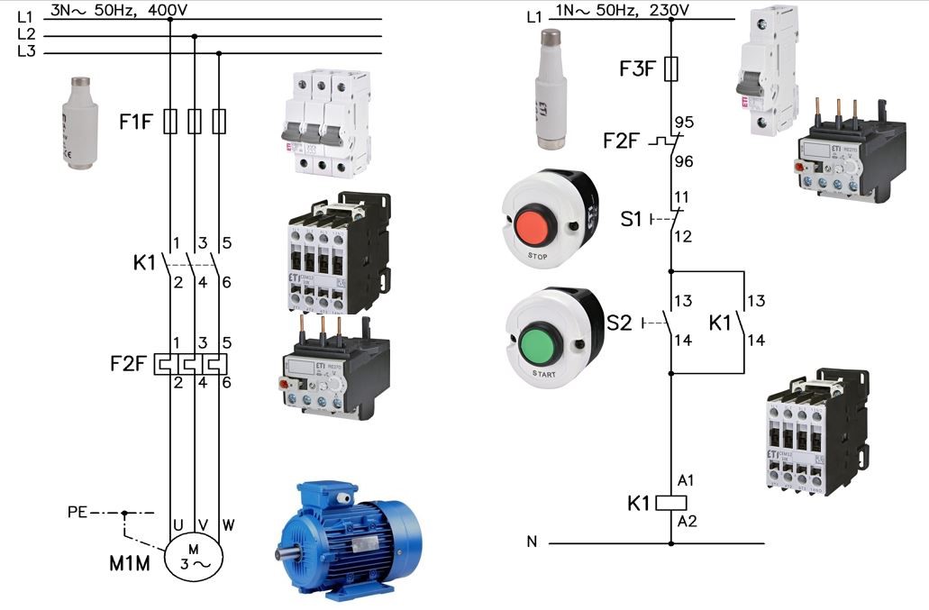
Figure 1: Remote switching on and off of a three-phase asynchronous motor
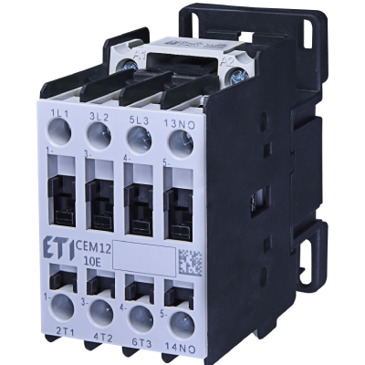
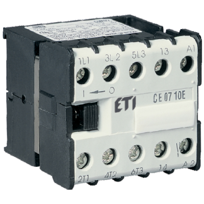
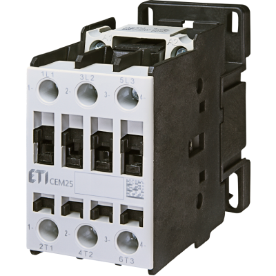
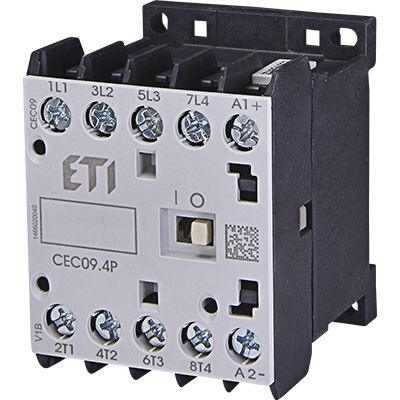
Figure 1 illustrates the remote switching on and off of a three-phase asynchronous motor using push buttons. The left part of the diagram shows the power section, or the three-phase circuit of the main power lines, while the right part depicts the control circuit. In addition to symbols, images of actual circuit components are included. The motor (M1M) will be turned on or off using push buttons. A three-phase asynchronous motor can be connected in either a star or delta configuration. The rated current of the motor must be known to correctly set the bimetallic relay (F2F), which protects the motor from overload. For short-circuit protection, three fuses (F1F) are used, though a three-pole circuit breaker of type C can also be used to avoid unnecessary tripping during startup. The diagram includes L1, L2, and L3 phase conductors, while PE is the yellow-green protective conductor, as the motor must be grounded. K1 is the contactor, an electromechanical switching device that connects the motor to the network remotely. The contactor must be of type AC3, as it handles higher starting currents.
Let's look again at the separate control circuit shown in Figure 2.
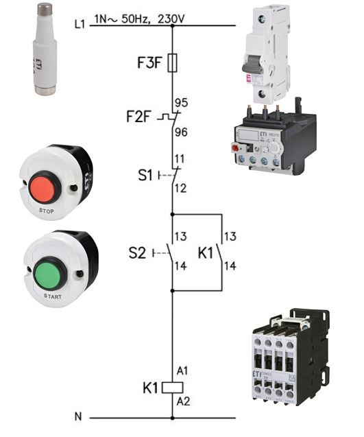
Figure 2: Control circuit with images of actual components
The control fuse F3F (or circuit breaker) protects the control circuit from short circuits. Let’s consider how to connect the control circuit. Start from the L1 source to the control fuse (or circuit breaker) F3F, then proceed to the normally closed (NC) contact 95,96 of the bimetallic relay F2F. This contact is often referred to as "normally closed" (NC). From contact 95,96, proceed to the normally closed (NC) contact 11,12 of push button S1. This push button S1 serves as the stop button and is red. Next, connect to push button S2, which serves as the start button and is green. Use the normally open (NO) contact 13,14. Push buttons typically have two contacts (one NO and one NC); select the one needed. From the NO contact 13,14 of push button S2, connect to the excitation coil of the contactor A1, and from A2 to the neutral conductor. The excitation coil is designed for 230 volts AC, although excitation coils are often designed for 24 volts DC. If the normally open (NO) contact 13,14 of contactor K1 is not connected, the contactor will remain active only while the green push button S2 is pressed. This makes the circuit without the 13,14 contact of K1 practically inoperative.
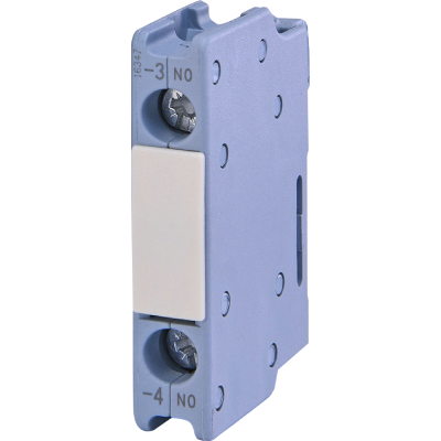
Now we will connect the normally open (NO) auxiliary contact 13,14 of contactor K1 in parallel with contact 13,14 of push button S2. What happens? When push button S2 (green) is pressed, the excitation coil (A1-A2) of contactor K1 receives 230 V. The main working contacts of contactor K1 close, connecting the motor to the three-phase AC supply and starting the motor. Simultaneously, the normally open (NO) contact 13,14 of contactor K1 closes. This contact keeps the contactor energized even after push button S2 is released, hence it is called the self-holding contact. Through this contact, the excitation coil A1-A2 of contactor K1 remains energized, keeping the motor running (see Figure 1).
What about the power section? Figure 3 illustrates the separate power section from the control section.
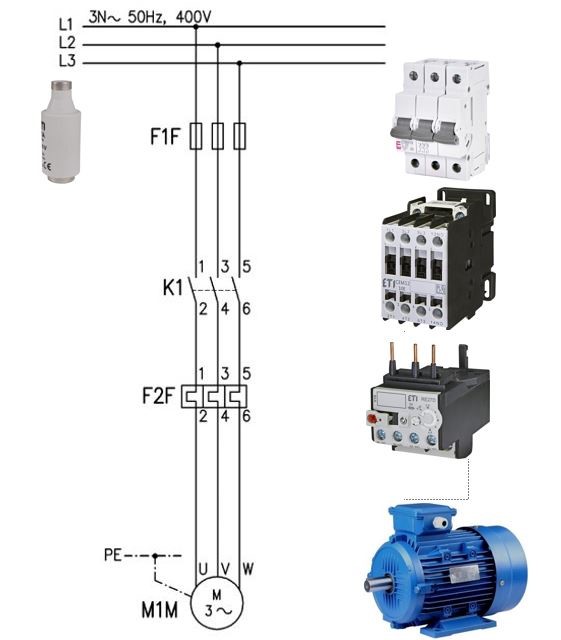
Figure 3: Power section or three-phase main circuit diagram
From the three phases L1, L2, and L3, connections pass through fuses F1F (or type C circuit breakers) to contactor K1, then to the bimetallic relay F2F, which protects the motor from overloads, and finally to the three-phase asynchronous motor. The bimetallic relay must be set to the motor's rated current. The three-phase asynchronous motor must also be grounded, and the neutral conductor is not required.
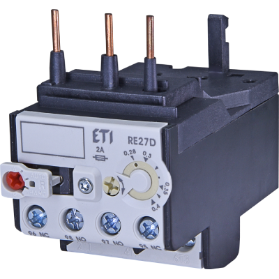
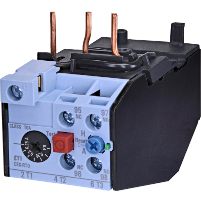
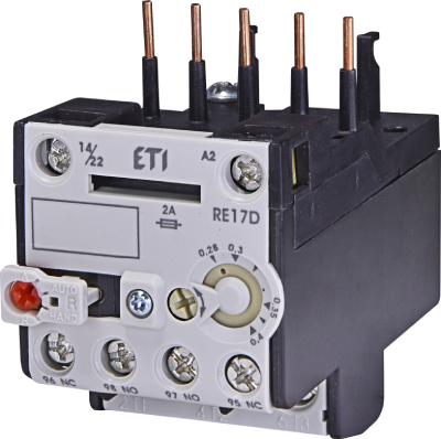
Pressing the green push button S2 turns the motor on, while pressing the red push button S1 turns it off. Let’s explain what happens during motor overload: Suppose the motor is driving a circular saw and encounters a knot in the wood, causing an overload. The current exceeds the motor's rated value, which could reduce the motor's lifespan or even damage it. The normally closed (NC) contact 95,96 of the bimetallic relay F2F (Figure 4) opens, stopping the motor immediately. Bimetallic relays can be with or without manual reset. Manual reset means that after tripping, the relay must be manually reset even after cooling. Without manual reset, the relay would reset automatically, potentially causing the motor to restart unexpectedly. For safety, using a relay with manual reset is preferable in such cases.
Figure 4: Bimetallic relay
Figure 5 shows the I-t characteristic (tripping characteristic) of the bimetallic relay, illustrating that at higher overload currents, the relay trips faster. For example, if the relay is set to 10 A and the overload current is 50% higher, the relay will trip in just over 2 minutes. If the relay was already warm, it would trip even faster.
Today, the combination of a fuse and a bimetallic relay is often replaced by a motor protection switch, while remote control using push buttons remains unchanged.
Figure 5: I-t characteristic of the bimetallic relay

