


TN Earthing System Regarding Grounding and Fault Protection
An important element in protecting people (including property and animals) from the effects of electric current is grounding the part – the point of the electrical power supply system (e.g., a 20/0.4 kV transformer station from which a building is powered) and grounding exposed conductive parts. The exposed conductive part (such as the stove housing) is normally not under voltage, but if the phase conductor comes into contact with the housing due to a fault, it can be dangerous if touched.
Depending on the grounding connection, the following power systems are allowed:
- TN
- TT
- IT
The type of allowed power system is determined by the electricity distributor in their network connection approval. This approval is issued before the building permit and must be followed by both designers and electrical installation contractors. Since the TN system is most commonly used in low-voltage distribution networks and both TN and TT systems prevail in low-voltage electrical installations, this article will focus on the TN power system.
TN Power System
In the TN system, three types of this system predominate, depending on the arrangement of the neutral and protective conductors, as shown in Figure 1.
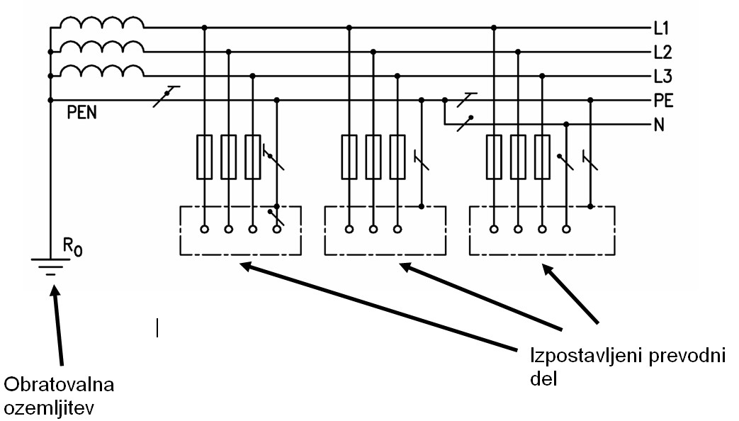
Figure 1: TN-C, TN-C-S, TN-S system
Let's now explain what each designation means:
- The first letter in the designation represents the relationship of the power supply system to the earth; the letter "T" indicates that the neutral point of the transformer (the star point of the low-voltage winding of the three-phase transformer) is directly connected to the ground. The connection to the ground is typically made with a galvanized steel bar in the form of two rings and four branches. This grounding is located in the ground beneath the transformer station at the appropriate depth.
- The second letter represents the relationship of the exposed conductive parts of the electrical installation to the ground; in our case, the letter "N" means that the exposed conductive parts are directly connected to the earthed point of the power system – the neutral point of the transformer (see Figure 1).
- The letter "C" means that the protective and neutral functions are combined in a single conductor – the PEN conductor. (C - combined)
- The letter "S" means that the protective and neutral functions are performed with separate conductors: N - neutral conductor (blue) and PE - protective conductor (green-yellow insulation) (S - separated).
The PEN conductor (protective neutral conductor) is an earthed conductor that performs the function of both the protective and neutral conductor simultaneously (see Figure 1). It must have a cross-sectional area of at least 10 mm² if copper, or 16 mm² if aluminum. When the PEN conductor is split into N and PE conductors at a certain point in the electrical installation, they must not be reconnected. At that point, the N conductor must not be connected to any other earthed part of the installation.
Figure 2 shows a branched electrical installation. The distribution board RG is supplied from the transformer station with a four-core cable (L1, L2, L3, PEN), and some sub-distribution boards are also supplied with four-core cables with a cross-section greater than 10 mm². Therefore, the label on the RG distribution board will be TN-C. The R1 distribution board is supplied with a four-core cable, and the smaller sub-distribution boards are supplied with five-core cables (L1, L2, L3, N, PE). The label on the R1 distribution board will be TN-C-S, as the PEN conductor is split into N and PE conductors at this board. A five-core cable with a cross-section smaller than 10 mm² supplies the sub-distribution board R2, from which various single-phase consumers with smaller cross-sections are powered. The label on this distribution board will be TN-S, as there is no PEN conductor at the input.

Figure 2: Powering different distribution boards and consumers in part of the electrical installation – explanation of when the distribution board is labeled TN-C, TN-S, or TN-C-S
TN Power System - Fault Protection
In the TN system, fault protection is provided by the following devices:
- Overcurrent protection (fuse, circuit breaker)
- Residual current protection (RCD)
TN with Overcurrent Protection (fuse, circuit breaker)
In the case of the TN power system, automatic disconnection of the power supply with overcurrent protection (fuse, circuit breaker) must be calculated by the designer to ensure proper protection in the event of a fault, and the inspector must confirm the designer's calculation by measurement during the inspection of the electrical installation.
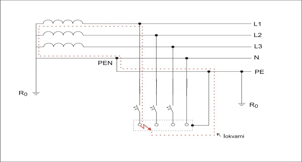
Figure 3: TN system – Fault protection with circuit breakers
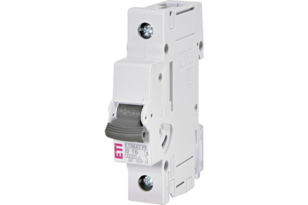
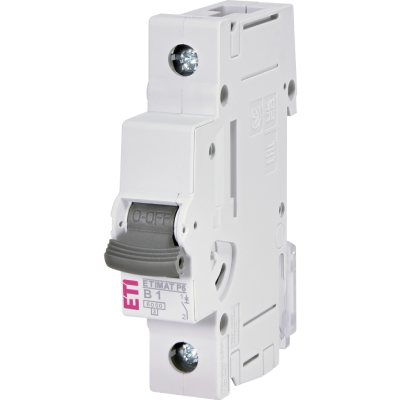
Figure 4: Circuit breaker, type B16 A, which trips in case of a fault (see Figure 3)
Figure 3 illustrates an example of a fault in the TN system with overcurrent protection (in our case, a circuit breaker – see Figure 4) on an individual device or consumer (e.g., a live conductor comes into contact with the stove housing, which could be very dangerous for the user). The fault current flows through the stove housing, through the protective conductor (PE conductor), then through the PEN conductor to the transformer station, and back to the low-voltage winding of the transformer and the phase conductor (through the low-voltage network and the low-voltage installation itself) to the consumer. This forms the electrical circuit of our fault current. All metal housings of electrical devices are grounded through the protective conductor, which has yellow-green insulation. The size of this current is practically the same as it would be in a single-phase short circuit between the L and N conductors, but the difference is that the fault current flows through the PE conductor. The current flows where the resistance is the lowest, so the current through the grounding at the object is negligible.
The fundamental requirement for protection with automatic disconnection of the power supply in the TN system is that the characteristics of the protective device and the impedance of the circuit are chosen so that, in the event of a fault between the phase and protective conductors or exposed conductive parts anywhere in the installation, the power supply is automatically disconnected within the specified time. The fault loop impedance must be low enough for sufficient current to flow to break the circuit (disconnect the protective device) within the prescribed time. This protective measure with automatic disconnection of the power supply in the event of a fault prevents the maintenance of dangerous touch voltage for a time long enough to be dangerous to the user. This requirement is met by the condition:
ZS × Ia ≤ U0
Where:
- ZS is the fault loop impedance, which includes the voltage source (low-voltage winding of the transformer), the phase conductor to the point of fault, and the protective or protective-neutral conductor between the fault point and the voltage source (see Figure 3).
- Ia is the current that ensures the operation of the protective device for automatic disconnection within the prescribed time (e.g., for socket circuits that do not exceed 32 A, the time must be less than 0.4 seconds; for distribution (supply) circuits and final circuits above 32 A, the time must be less than 5 seconds) when the phase voltage is 230 V and the line voltage is 400 V.
- U0 is the nominal voltage to the ground (e.g., 230 V).
In our case, we can expect the circuit breaker to disconnect the power supply in less than 0.4 seconds in the event of a fault.
TN System with Residual Current Device (RCD)
RCD-protective devices (residual current devices) are installed as disconnecting devices even in TN systems, as their use is mandatory in some circuits (e.g., circuits in bathrooms, sockets on construction sites, circuits in fire-hazardous areas, etc.). Sometimes, it is not possible to ensure a sufficiently short disconnection time, and in such cases, an RCD can be helpful.
When protecting a TN system installation with an RCD, protection is achieved by connecting all exposed conductive parts of the equipment to the protective conductor on the supply side of the residual current protection device (the PE or PEN conductor is used as grounding — see Figure 5).
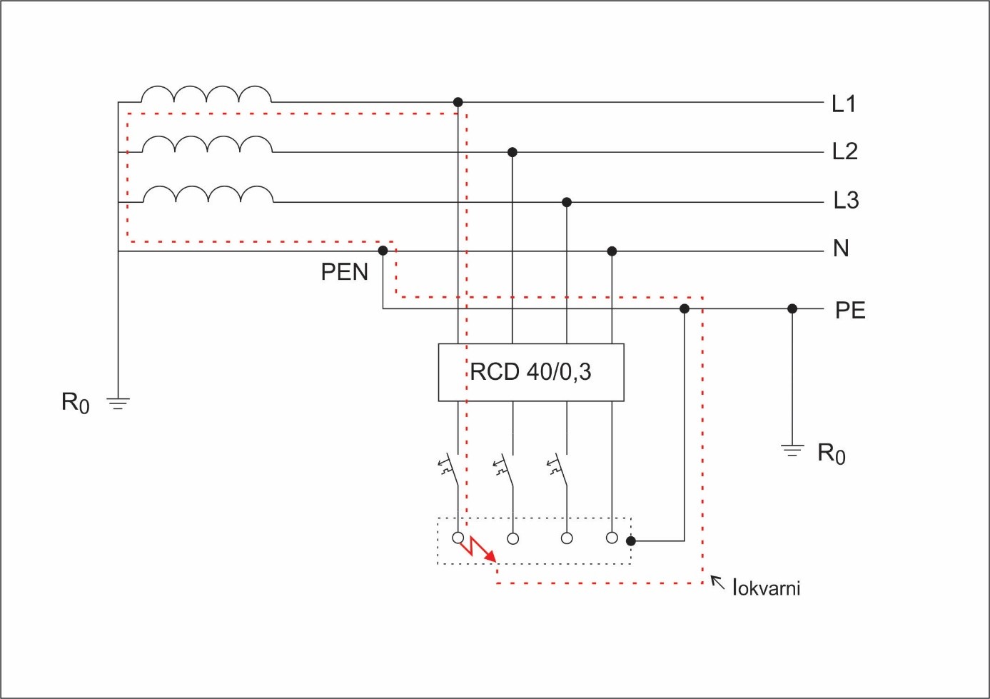
Figure 5: Fault Current Path in a TN System with an RCD
In a TN installation system, a fault current powered by the phase voltage is conducted from the damaged equipment through the protective (PE) and protective-neutral (PEN) conductor, through the neutral point in the power source — the transformer — into the phase winding of the phase that powers the fault location. This path has an impedance ZS, which is the impedance of the fault loop. In this case, the following inequality condition must be met:

where the terms represent:
- ZS ... fault loop impedance in Ω,
- IDn ... rated residual current of the residual current device (RCD) in A,
- U0 ... nominal voltage to earth in V.
From the inequality, it follows how high the fault loop impedance can be in relation to the rated residual current of the installed RCD.
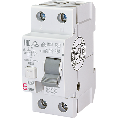
Since the actual impedance is very low (< 2Ω) and the rated residual current is also small (e.g., 300 mA), the inequality condition is easily met. The only potential issue could be a broken protective conductor, which can be checked through measurement. Protection is then verified by checking the operation of the installed RCD, which must disconnect the installation at the rated residual current of the RCD (with U0=230 VU_0 = 230 \, VU0=230V) within t≤0.4 st \leq 0.4 \, st≤0.4s, which is easy to achieve when using RCDs. Prior to this, the mechanical operation of the switch is checked using the test button located on the RCD (see Figure 6).
In the RCD (Figure 5), an electrical current imbalance occurs, as the sum of incoming currents is not equal to the sum of outgoing currents, and the RCD disconnects in less than 30 ms, which is crucial for the safety of people. The difference in currents is known as the residual current.
If the residual current exceeds the value required to trigger the RCD's disconnection mechanism, the RCD will disconnect the circuit. In Figure 5, a four-pole RCD switch (40 A/0.3 A) is shown, with a rated residual current (I_Dn) of 0.3 A. In this case, the RCD will disconnect between 0.15 A and 0.3 A (if it is type AC). Since the fault current is significantly higher, the disconnection is immediate.
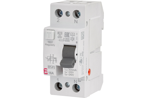
Figure 6: Example of a 2pole RCD of type A with a rated residual current of 0.3 A