Utility-scale Battery storage system
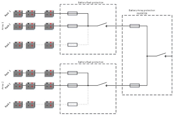
Battery storage system is a system of serial and parallel-connected battery cells. In a battery rack are serial-connected battery modules and in battery array are parallel-connected battery racks. Battery racks are usually containerized and electrically combined inside d.c. combiner boxes, protected with fuse-links. Battery containers are then connected to the battery inverter, electically combined in an inverter d.c. combiner box protected with fuse-links.
| Anže Jerman Product manager |
Battery storage system is a customized system, which means rated voltage, capacity and discharge rate are projected according to the customer requirements. Depend on project requirements correct fuse-links should be used. The following document is prepared for the explanation of important parameters which should be considered for battery storage protection.
Figure 1: Battery storage system architecture
.jpg)
The example of a battery storage system
Connection topology and used values are just informative to show an example.
| Battery system: | |
| No. of parallel arrays | 2 |
| Rated voltage d.c. | 1500V |
| Rated current | 2x400A |
| Rated power | 1,2 MW |
| Capacity | 600kWh |
Figure 2: Topology of 1,2 MW battery storage system
Resistance of a battery system
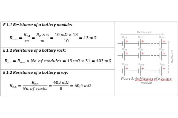
One of the most important parameter is the resistance of a battery cell. The range of resistance is between 0,5 to 10 mΩ per cell. Depends on the resistance of a battery cell prospective short‑circuit current can be calculated. Prospective short‑circuit current depends on the resistance of the battery cell and the resistance of connection conductors. In the worst-case scenario should be taken just the resistance of a battery cell.
| Battery Cell: | |
| Rated voltage d.c. | 3,7V |
| Capacity | 2500mA |
| Discharging rate | 2C |
| Resistance | 10mΩ |
Prospective short-circuit current
Prospective short-circuit current is calculated from Ohm's law. In the equation should be used a rated voltage of battery system and resistance of battery system depends on the location of a short-circuit. In basic, there are two possible locations of short-circuit current, inside battery racks and battery arrays.
Battery Rack protection
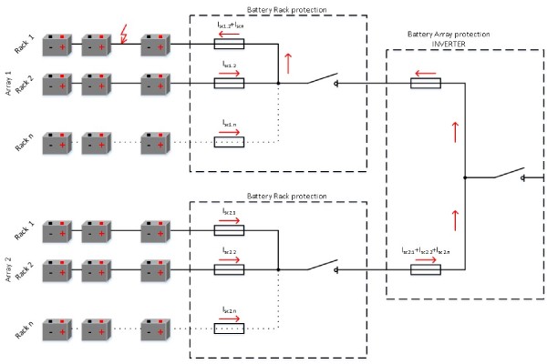
Battery racks are electrically combined in d.c. combiner boxes. In case of fault inside of a battery rack, a short‑circuit current will be the sum of a battery rack currents in the fault array. Battery racks are protected with fuse-links dimensioned according to the nominal current of a battery rack. The breaking capacity of fuse-links should be higher than the sum of prospective short-circuit currents of each battery rack in a battery array.
| Battery Rack: | |
| NO. of serial modules | 31 |
| Rated voltage d.c. | 1500V |
| Rated current | 50A |
| Rated power | 75kW |
| Capacity | 37,5kWh |
| Discharging rate | 2C |
| Resistance | 403mΩ |
| Prospective short-circuit current | 3700A |
Prospective breaking capacity of a battery rack protection:
Figure 5: Short-circuit current inside battery rack
Battery Array protection
Battery arrays are electrically combined in an inverter d.c. combiner box. In case of fault inside of a battery array, the short‑circuit current will be the sum of battery array currents. Battery arrays are protected with fuse-links dimensioned according to the nominal current of a battery array. The breaking capacity of fuse-links should be higher than the sum of prospective short-circuit currents of each battery array in a battery system. Reliable protection on a battery array level could be provided with several separated fuse-links, parallel-connected on the d.c. busbar.
| Battery Array: | |
| No. of parallel racks | 8 |
| Rated voltage d.c. | 1500V |
| Rated current | 400A |
| Rated power | 600kW |
| Capacity | 300kWh |
| Discharging rate | 2C |
| Resistance | 50,4mΩ |
| Prospective short-circuit current | 29.800A |
Prospective breaking capacity of a battery array protection:

Conclusions
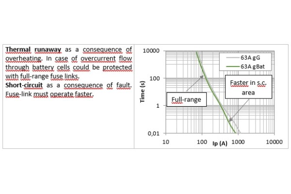
Because of the architecture of a Battery storage system, battery racks and arrays should be protected against damages in case of short-circuit current. This document shows the importance of high-level breaking capacity which could be reached protected with fuse links. With the development of battery cells, the resistance of cells is even lower. Because of that, a high-level breaking capacity of the protection device is required.The document shows that the correct architecture of a Battery storage system could avoid unwanted scenarios which could provide unwanted damages in the system.


